Abstract :
As a Automobile engineering students the team has decided to test our knowledge
in Automotive field by building a prototype four-wheel, two passenger, On road car
. The engine, brake system, fuel system and steering mechanism must be of adequate
measures and strength to run and protect the operator in the event of a rollover
or impact. The roll cage must be Constructed of steel tubing, with minimum
dimensional and strength requirements dictated by Society of Automotive
Engineers(SAE). The Increased concern about the roll cage has created the
importance of simulation and analysis thereby predicting failure modes of the
frame. In the present paper, We have used solidworks to Investigate the response of the frame under
various impacts. We considered a direct frontal impact and side Impact that
result in a 4g horizontal loading, a rollover impact of 3g deceleration value, bump
impact and Front torsional impact analysis with 3g deceleration value. The
impact loading is simulated by restricting Displacements at certain locations, and
applying discrete forces at various points on the frame where the Weight is
concentrated. Throughout analysis of roll cage is done more emphasis was given
on obtaining allowable Factor of safety and designed according to it.
Keywords: roll
cage; frontal impact; side impact; rollover impact; Solidworks
It gives a clearer vision
of how the project is organized. As shown in (fig), at the appendix, the
lifecycle includes six stages: project plan, product redesign, manufacturing
process design, competition, maintenance, recycle and disposal .The present
design report explain only two stages, the first one which is the product design
and the third one the manufacturing process design. The design stage is based
in the dynamic analysis of the components, strain-stress results, deformation
results, and fatigue, but also taking in consideration and easy
manufacturability and low cost .The objective of the design is to create a
durable, safe and easy to maintain vehicle that is able to deal with in any weather
condition. Because there is a separate report which deals with costs of parts
and manufacturing details, this report will only consider costs when it becomes
a crucial factor in a design decision.
A frame of a
vehicle plays the most important role in safety of the passenger. The frame
contains the operator, Engine, brake system, fuel system and steering mechanism,
must be of adequate strength to protect the operator in the event of a rollover
or impact. The passenger cabin must have the capacity to resist all the force
exerted upon it. This can be achieved either by using high strength material or
better cross sections against the applied load. But the most feasible way to
balance the dry-mass of roll-cage with the optimum number of members is done by
triangulation method. The roll cage must be constructed of steel tubing, with
minimum dimensional and strength requirement dictated by solidworks. Circular
cross-section is employed for the roll cage development as it helps to overcome
difficulties like increment in dimensions, rise in the overall weight and
decrease in fuel efficiency. It’s always a perfect one to resist the twisting
and the rolling effects, therefore is preferred for torsional rigidity
Material
|
1018
steel
|
Outside
Diameter
|
2.2
|
Wall
Thickness
|
0.086
|
Bending
Stiffness
Bending
strength
|
|
Weight
Per meter
|
3 kg
|
a) Design objective of roll cage
are:
1)
Provide full safety to the driver , by
obtaining required strength and torsional rigidity , while reducing weight through
diligent tubing selection.
2)
Design for manufacturability , as well
as cost reduction , to ensure both material and manufacturing costs
3)
Improve driver comfort by providing more
lateral space and leg room in the driver compartment
4)
Maintain ease of serviceability by
ensuring that roll cage member do not interfere with other subsystem
This
roll cage is developed in solidworks weldments and simulation menu by plotting
the keypoint , line and arcs . The element type selected for it is SCH 20 , a
uniaxial element with tension , torsion and bending capabilities .The element
has six degrees of freedom at two nodes : translations in the nodal x , y and z
Directions
and rotations about the nodal x , y and z axes . The real is constants involved
in the pre-processing of SCH 40 elements
are its outer diameter and thickness
value . The material used for the roll cage is AISI 1020 with young’s modulus
210 GPa ; yield strength is 365.5 MPa and poissons’s ratio 0.29.The density of
material is 8000kg\m3 with hardness(Brinell) of 126 HB[7]
2. Meshing
and analytical calculations
a) Meshing constraints and
calculations
As the roll cage
was developed by plotting key points, lines and splines, so every member of the
roll cage is considered to be properly constrained at every joint. For boundary
conditions for frontal impact test, the roll cage is to be fixed from the rear
side and front member will come across applied load. In the similar way, for Side
impact test, one side of the roll cage elements are fixed while the other side
will be applied with load. For rollover impact test, the lower elements of
the roll cage is fixed. For bump impact
test and torsional impact test , the roll cage is to be fixed from the rear
side .The load will be distributed among the number of joints framed by front
members in the opposite direction to the frame , i.e X axis
b) Analytical calculations for determining impact
on roll cage
To
properly analyse the impact force , we need to find the deceleration of the vehicle
after impact .To approximate the worst case scenario that the vehicle will
undergo , momentum equations were used to determine the deceleration of the
vehicle. The vehicle was considered to be at maximum speed of 60 km\hr having
total weight of 550 kg and according to different scenarios the conditions of
head on Impacts, oblique collisions ,and inelastic or partially elastic
collisions were employed with a crash pulse Consideration of 0.1s.
The forces which were impacted on the
roll cage were decelerations of 4g and 3g and it is calculated as follows:-
Assume gravitational force=9.8 m/s2=10
m/s2
g=mass of the
vehicle * gravitational force acting on the vehicle
Therefore,
4g=18,000 N and 3g=13,500 N.
3. Impact Analysis Using Solidworks
a) Frontal
Impact Analysis
It is the impact
wherein there is possibility of vehicle crashing into another vehicle head or
in the hard surface . The deceleration value for frontal impact is 4g.This is
equivalent to a loading force of 18,000 N .The load applied on two nodes at front as shown by red
arrow(Fig.) .Thus , a force gets divided into two parts i.e 9,000 N on each
node .The value recorded for the deformed shape is 1.343 mm (Fig.) which abides
by the safety regulations(Fig.).shows the von misses stress plot ,where the maximum
stress is observed at the front members(11.114 Mpa) where the load is applied .The
driver cabin member are shown in yellow and green colour which clearly depicts
the safety of driver cabin even when loaded with such high force
a) Side Impact
Analysis
The side impact analysis is carried out
as there is a possibility of collision with another vehicle from either
direction .Thus, the stress acting on the side members of the roll cage are
analyzed. The deceleration value for side impact 4g.This is equivalent to a
loading force of 18,000 N .The load is applied on two nodes shown in (Fig.3) Thus
,the force on each node is 4500 N. The nodal solution shows a deformation of mm in coloured contour as shown in (Fig. ).The
Von Mises stresses came out to be 22222 MPa which is inside the permissible
range of the material(Fig. ).The driver cabin members are shown in green colour
which reflect the safety of driver cabin even when such a high load is
introduced.
b) Rollover Impact Analysis
The rollover impact analysis is carried out by
considering the stresses induced on the member of the roll cage when the
vehicle topples down from a slope with an angel of 45o.In this impact ,the upper and rear
members of the vehicle will bear the force .The deceleration value for rollover
impact is 3g.this equivalent to a loading force of 13,500 N. The number of
nodes on which the load is applied is 4.Thus 4,125 N was applied on each node .The
maximum deformation is 1.35e mm in the members of the vehicle in (Fig .). The
Von Mises Stress induced on the members is shown in (Fig .). The maximum stress
i.e. MPa was observed at the upper
members of the vehicle which is well below the permissible range.
c) Two Wheel Bump Impact Analysis
The vehicle has to travel on
uneven tracks .There are times when the vehicle moving along an upward slope
travels about a curved projectile in air before landing on its wheel .The lower
frontal part of the vehicle’s the initial member which faces this impact .Once
the front tyres touch the surface, the suspension system absorbs the initial
forces exerted on it .A times comes when the suspension system are compressed
to its maximum extent and act like solid member of the vehicle. The rest of the
load is transferred to the roll cage members of the vehicle[9].In order to
ensure the safety of the driver ,we determine this impact force using
Solidworks.
The deceleration
value for bump analysis was taken as 3g i.e. 13,500 N .The force was applied on the
frontal four suspension pick up point
(Fig. ).The load applied on each node
was 4,125 N. The deformation value is
mm which abides by the safety regulations .The von Mises Stresses is
plotted in (Fig. ) showing the
individual stresses in the members .The maximum stress as observed was found
out to be MPa which is within the
permissible limit of the materials yield strength.
d) Torsional Impact Analysis
This impact is analyzed taking into
consideration the torsional forces acting on the frontal elements of the
vehicle .This type of force is exerted on the vehicle when it traverses on an
uneven road .The two tyres on the front axle experience a moment .The torque is
applied to one tyre and reacted by the other one(Fig. ) These forces are equal
and opposite .The deceleration value for this impact is 3g i.e. 13,500 N .But
as these act in opposite direction ,the number of nodes for application of
force is 2.The amount of force per node is 8,250 N.
The deformed value after analysis is
1.543 mm as shown in (Fig.).The maximum Von Mises Stress in this analysis came
out to be 7.777 MPa which lies within the permissible range of the material
(Fig. ).
SUSPENSION
OBJECTIVE:
The suspension is responsible for
dissipating the energy obtained from the impacts that are caused by the uneven
terrain .It is also responsible for maintaining the vehicles stability and ride
height when managing obstacles. Another point is to reduce vibration for the
vehicles durability and drives comfort.
DESIGN:
The rear suspension was a major
improvement in design over the previous car. A pushrod double A-Arm suspension
was opted in order to work in conjuction with the drive train, as shown in
(fig.6).This configuration gives us better bump absorption due to its long
trailing and adjustable suspension geometry. We are using a 1018 steel seamless
tube with 1inch OD 5mm wall thickness.
The front suspension works with a
double A-Arm system. The upper A-Arm is shorter than the lower A-Arm, so the
camber angle can be maintain throughout dynamic movement of suspension. The
front suspension equipped with two spring loaded dampers to manage the rocks,
bumps and other obstacles while maintaining good traction. Fig(.7) shows the analysis made with
solidworks simulation to prove the resistance the A-Arms considering a4.448kN(1000
lbf)
STEERING SYSTEM
OBJECTIVE:
The steering sub system
is responsible for the control of the vehicle. In the design process of this
sub system the goal is to achieve a small turning radius and steering
stability. The speed of response and the driver’s input are also prime factors
for the design of the steering system.
DESIGN:
The steering system works
with a maruti Suzuki 800 On-road rack and pinion. The rack travels one and a
half turns from lock to lock which allows good control of the vehicle and good
responding speed. The rack is connected to 2 Tie-rods working in front of the
shocks for reduced weight. The rack travels 7.62cm (3inch) from lock to lock to
make the wheel turn. The front wheels configuration has a -3o camber angle and an 5o caster angle. The caster tends to drive
the wheels forward, which makes it easier to maintain the car in a straight
direction, also inclination of the knuckle helps to reduce the turning radius.
DRIVETRAIN
OBJECTIVE:
The objective of the
drivetrain is providing to the driver more than the enough torque to the wheels
from the engine to the wheels. The calculations were made in order to select
the proper components that satisfy an operator and to provide the car the
enough strength to climb a 60o
incline.
DESIGN:
The main components of the
drivetrain is the maruti Suzuki 800 engine which gives 37 bhp at 5000 rpm and
59 Nm at 2500 rpm
CENTRE OF GRAVITY
Also we evaluate the gravity
centre of the car, as shown in fig(.9) in order to reach the closes value to 60o between the GC of the car and the rear
axle to obtain stability.
BRAKE SYSTEM
OBJECTIVE:
The breaking
system of the “VELOCY 5” is designed to lock all four wheels quickly to provide
safe breaking.
DESIGN:
For the breaking system we used
two independent hydraulic system, both working with maruti Suzuki 800 19.05mm master cylinder and a single pedal.
The master cylinders make a cross connection, each controlling a front wheel
and a opposite rear wheel as shown in (fig.9). By working in this way can
ensure that in event of failure of one cylinder the car wheel not tend to turn
out of the road. All four wheels have a caliper with rotors to provide breaking
force. The pedal has length of 38.1cm(15inch) from foot position to bias bar contact,
which makes it easier to provide enough breaking force.
GUARDS
OBJECTIVE:
The
main objective of the guards and body panels is to keep the drivers safe debris
and mechanical system, among other things.
MATERIAL SELECTION:
All of the body panels, as
well as the firewall and roll cage guards are made of sheet. We use a 0.508mm
(0.020inch) thick sheet to reduce weight while maintaining resilience in the
panels. The skid plate is made out of textured sheet with a thickness of
1.651mm (0.065inch) to provide good support for the driver and to ensure good
grip at all times. All of the moving parts in the drivetrain are covered with
regular 1010 steel expanded metal 1.27cm (1/2inch) #16 3.988mm (0.157inch)
thickness case, which provides excellent protection in case of drivetrain
failure.
Table 2 is a comparative
of different materials selected as options for the drivetrain guards, based on
weight and energy absorption at rupture as shown in fig(.88)
Result And Discussion of chassis stress level
Table
3. Analysis results of impact tests
Factor of safety
(FOS)
|
Von Mises stress
(MPa)
|
Maximum
Deformation
(mm)
|
Number of
Nodes
|
Loading
Force(N)
|
Type of
Impact test
|
Point A
|
6.87
|
1.6
|
2
|
18,000
|
Front
|
Point B
|
7.6
|
2.0
|
2
|
18,000
|
Side
|
Point C
|
6.2
|
1.4
|
4
|
13,500
|
Roll-over
|
Point D
|
7.1
|
1.87
|
4
|
13,500
|
Bump
|
Point E
|
4.2
|
1.5
|
2
|
13,500
|
Torsional
|
CONCLUSION
The
process of designing a vehicle is not a simple task; as a matter of fact it
takes lot of effort from all members of the team to achieve a successful
design.
The
final prototype was the product of a collaborative multidisciplinary team
design. The goal of the project was to create an on-road recreational vehicle
that met or exceed the SAE regulations for safety, durability and maintenance,
as well as to achieve a vehicle performance, aesthetics and comfort that would
have mass market appeal for the on-road enthusiast. All of the design decisions
were made keeping these goals in mind.
The
selection of components were made using engineering knowledge achieved through
with on- road enthusiast and engineering advisors, taking as parameters first
of all, safety, performance, weight, reliability and last of all cost. To
see an overall technical description of
the “VELOCY5” see Table 5. Computational design became the most important part
of the process; by using CAD software we were able to print our ideas before
constructing any prototype, plus the CAE packages and FEA allowed the team to recreate
actual working conditions of some of the subsystems to ensure their durability.
APPENDIX ENGINE
|
Model
|
0.8 LITRE OHC , 2
VALVES/Cylinder, 3 cylinder
|
Displacement
|
796 cc
|
Compression Ratio
|
9:01
|
Power
|
38 BHP@5000rpm
|
Torque
|
59Nm@2500rpm
|
DIMENSIONS
|
Overall Length
|
3300mm
|
Wheel Base
|
176.53cm (69.5in)
|
Overall Width
|
161.29cm (63.5in)
|
Ground Clearance
|
35.56cm (14in)
|
Weight
|
450kg
|
SUSPENSION
|
Front Suspension
|
Double A-arm,
26.67cm (10.5in) travel
|
Rear Suspension
|
Double A-arm,
17.78cm (7in) travel
|
Front Shocks
|
hydraulic Shocks,
11.43cm (4.5in) travel
|
Rear Shocks
|
hydraulic
Shocks,11.43cm ( 4.5in) travel
|
STEERING
|
on-road Rack &
Pinion
|
Rack 8.89cm
(3.5in) travel
|
Camber Angle
|
-2.0°
|
Caster Angle
|
5°
|
WHEELS AND
TIRES
|
Front Wheels
|
Steel pressed
wheels
|
Rear Wheels
|
Steel pressed
wheels
|
Front Tires
|
175/75 R13 Tires
|
Rear Tires
|
175/75 R13 Tires
|
BREAKS
|
Master Cylinder
|
Maruthi800® 19mm
|
Calipers
|
Maruthi800 solid
disc w/rotors
|
|
|
PERFORMANCE
|
Max speed
|
140kmph (82mph)
|
Turning radius
|
4.5m (177in)
|
 This was the starting i had to paint the engine mounting to red 😜 motivation symbol red ? and by the the engine is a 800cc 3 cylinder one . you can see the gear shaft linkage connected to the shifter the conversion is going to be the shift linkage to the front as this vehicle is a mid engine 😕
 This is the main spaceframe which adds the maximum intregity for the vehicle .traingulation has to be done. people may say "why a arc weld " this project was mainly to test my skills in designing and manufacturing a vehicle so this vehicle is pretty budget friendly . i had to learn arc welding techniques it was a tedious job hours of weld passes . the pipe which i used is pretty thin for a arc weld had to get the right angle, technique and amperage . phew!
 My colluegue just the base frame and the engine mounted still the suspension geometry has to be worked in my pc and give it life . we could dream our finished car 😄 theis place is my backyard quit a place to work with the nature 😝
 My dream was to keep atleast the front with a pushrod mechanism if not the rear . there was clearance issues in providing pushrod mechanism to the rear because of the track width the donor vehicle axles provided, we wanted to keep the cost as low as possible otherwise we would have got a custom size drive axles for the rear .

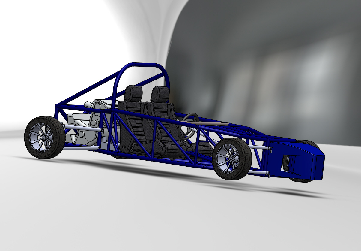
 This i had to check for the clearance of having a middle section for the gear shifter and seats .
 It was almost in a complete state still had to do the radiator , pedals cables , wiring cable management , seat mounts , floor panels , guards and some tweaks here and there. there are a alot of pics missing i will upload it soon guys 💪
 looks mean right i loved it with only the primer coat 💓